
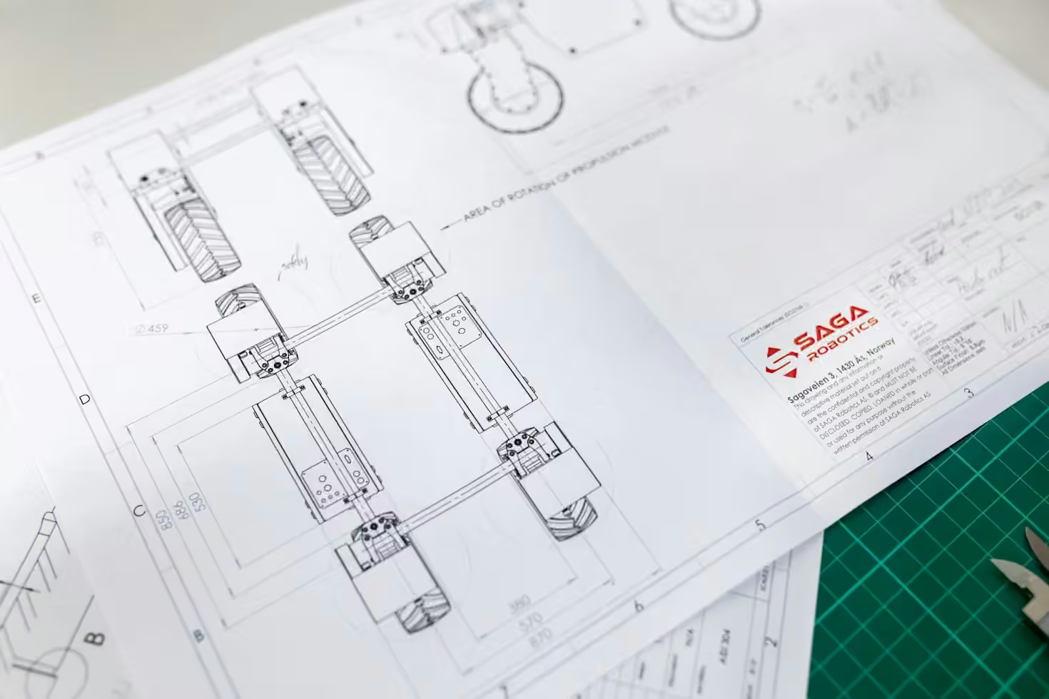
Learning how to read electrical plans for estimating is one of the most important skills an electrical estimator can develop. Plans contain the complete scope of electrical work  fixtures, wiring, panels, conduit, equipment, and control systems. Missing even one element during takeoff produces an inaccurate estimate and potential cost overruns.
This guide walks through the process of reading electrical plans efficiently and accurately.
Understand the Plan Structure
Electrical plans are part of a larger construction document set. Familiarize yourself with the full package before diving into takeoff:
- Cover sheet: Project name, address, architect, engineer, and revision history
- Electrical legend: Symbols, abbreviations, and line types used throughout the plans
- Power plan: Outlets, receptacles, equipment connections, and circuiting
- Lighting plan: Fixture types, locations, switching, and controls
- Panel schedule: Panel types, circuits, loads, and breaker sizes
- Riser diagram: System hierarchy from service entrance to final circuits
- Detail sheets: Close-up views of special installations, connections, or equipment
- Specifications: Technical requirements, materials, and installation standards
Start with the legend and specifications. They define the symbols and standards the plans use  misreading a symbol on day one cascades into incorrect quantities throughout the takeoff.
Learn the Electrical Symbol Library
Electrical symbols are standardized but vary by architect and project. The legend on each plan set defines the specific symbols used. Common categories include:
Lighting fixtures: Recessed LED, surface-mounted, exit signs, emergency lighting Receptacles: Duplex outlets, dedicated circuits, GFCI, floor boxes Switches and controls: Single-pole, three-way, dimmers, occupancy sensors Panels and equipment: Distribution panels, transformers, switchgear, disconnects Wiring and raceways: Conduit types, cable trays, wireways, busways
Verify each symbol against the legend. When in doubt, ask the architect or engineer for clarification before proceeding with the takeoff.
Read the Specifications Alongside the Plans
Specifications (the “spec book”) contain requirements that plans cannot show visually. Critical estimating details buried in specs include:
- Fixture manufacturers and model numbers
- Wire types and insulation ratings
- Conduit materials and fill requirements
- Panelboard brands and features
- Installation methods and clearances
- Testing and commissioning requirements
A plan may show a generic “panel” symbol, but the specification defines its exact type, rating, and mounting requirements  all of which affect cost.
Identify All Plan Sheets and Revisions
Before starting takeoff, confirm you have every sheet in the electrical set. Count the sheets listed on the index and compare against what you have received. Missing a sheet means missing scope.
Then check the revision block on each sheet. Plans may have been updated after initial issuance. Addenda, revision letters, and owner directives modify the original scope. Takeoff from an outdated sheet produces an estimate for work that no longer exists.
Use drawing comparison tools to highlight changes between revisions. Bluebeam Revu’s Compare tool overlays two PDF versions and marks every difference.
Takeoff in a Logical Order
A structured takeoff order reduces missed items and improves efficiency. Work through the plans in this sequence:
- Service entrance and distribution: Main panels, switchgear, transformers
- Branch circuits and wiring: Conduit runs, cable pulls, wire sizes
- Lighting: Fixtures, controls, switching, emergency lighting
- Power: Receptacles, equipment connections, dedicated circuits
- Low voltage: Data, communications, security, fire alarm
- Special systems: Generator, UPS, solar, EV charging
- Devices and accessories: Boxes, connectors, straps, ground bushings
Working through systems in order helps maintain focus and reduces the chance of skipping a category.
Count Quantities Methodically
Counting requires discipline. For each item type:
- Identify every instance on the plan
- Verify it against the symbol legend
- Record the quantity in your takeoff sheet
- Note any unusual conditions (height, access, special mounting)
For wiring and conduit, measure runs using the plan scale. Digital takeoff tools like PlanSwift and Bluebeam measure distances automatically  but verify the scale bar is correct before trusting measurements.
Cross-Reference Panel Schedules and Riser Diagrams
Panel schedules and riser diagrams confirm the scope you count on the plans. A panel schedule lists every circuit, breaker size, and connected load. Compare it against the fixture and receptacle counts on the power and lighting plans. Discrepancies indicate either a counting error or an incomplete plan set.
Note Dimensions and Clearances
Electrical installations require physical space. Plans show dimensions for:
- Ceiling heights and plenum depths
- Panel and equipment mounting locations
- Conduit routing through walls and ceilings
- Clearances around electrical rooms
A fixture shown on a plan at 12 feet above the floor requires lift equipment  a cost the takeoff must capture. An equipment room with limited access increases labor hours.
Identify Site-Specific Conditions
Site electrical work differs from interior installation. Site plans show:
- Transformer pads and utility connections
- Underground conduit runs and trenching
- Exterior lighting poles and site circuits
- Service entrance routing
- Grounding and bonding requirements
Trenching depth, soil conditions, and pavement restoration add cost that interior plans do not reflect.
Review the Estimate Against the Plans
After completing the takeoff, return to the plans and verify your quantities. Walk through each plan sheet and confirm your count matches what the drawing shows. This review step catches missed items before they reach the bid.
Frequently Asked Questions
What do the symbols on electrical plans mean? Symbols represent fixtures, devices, panels, wiring, and equipment. Each plan set includes a legend that defines the specific symbols used. Always reference the legend when taking off.
How do I measure conduit runs from plans? Digital takeoff tools like PlanSwift measure distances directly from PDF plans. Confirm the scale bar is correct before measuring. For complex runs, trace the path and measure each segment separately.
What should I do if the plans and specifications conflict? If plans and specs disagree, note the conflict and request clarification from the architect or engineer. Do not assume  bid based on the more restrictive requirement and document the discrepancy.
Need professional electrical estimating services? Apex Electric Estimating Inc reads every plan sheet, cross-references specifications, and delivers complete, accurate estimates in 24–48 hours through our electrical estimating services and material takeoff services. Email your plans to [email protected] or call +1 (862) 366-7732.